555 Timer Schematic / 555 Timer Tutorial And Circuits Build Electronic Circuits : 555 timer helpers schematic the addition of a capacitor to the trigger will not work for short output pulses as there is also a short delay in the recovery of the trigger terminal voltage.
555 Timer Schematic / 555 Timer Tutorial And Circuits Build Electronic Circuits : 555 timer helpers schematic the addition of a capacitor to the trigger will not work for short output pulses as there is also a short delay in the recovery of the trigger terminal voltage.. As discussed in the above section, the ic is in its standard monostable mode. The 555 is also very versatile, and can be used. This led will be switched on when button s1 is pressed and switched off when button s2 is pressed. Here is the practical demonstration of the bistable mode of 555 timer ic, where we have connected a led to the output of the 555 ic. The calculator simplifiers the voltage divider calculations just leave the unknown and fill out the rest.
The monostable circuit that we will build using a 555 timer is shown below. Circuits into the ever increasing ranks of timer users. A monostable 555 timer is required to produce a time delay within a circuit. The output voltage from the chip is around 1.5 v lower than vcc when high and around 0 v when low. The time intervals can be used for keeping a relay controlled load on or activated for the desired amount of time and an automatic switch off once the delay period.
555 Timer Tutorial The Monostable Multivibrator from www.electronics-tutorials.ws This pin connects to the negative side of the battery. The 555 timer is a chip that can be us… This circuit of this project makes the use of timer ic ne555 which produces a constant square pulse of a desired frequency. 555 timer is an industrial standard ic existing from early days of ic. The 555 timer ic is an integrated circuit (chip) used in a variety of timer, delay, pulse generation, and oscillator applications. The ic can operate in three different modes such as astable, monotstable and bistable, because of which it can be adapted into many types of circuit designs like time delay circuits, pulse generation circuit, oscillator circuit and much more. The standard 555 timer ic is made of 2 diodes. The 555 timer is a simple integrated circuit that can be used to make many different electronic circuits.
The output voltage from the chip is around 1.5 v lower than vcc when high and around 0 v when low.
The time intervals can be used for keeping a relay controlled load on or activated for the desired amount of time and an automatic switch off once the delay period. Basic 555 monostable multivibrator circuit. This tutorial provides sample circuits to set up a 555 timer in monostable, astable, and bistable modes as well as an in depth discussion of how the 555 timer works and how to choose components to use with it. The two mostly used modes of 555 are monostable and astable. We have a large collection of simple and advanced projects using 555 timer ic. 555 timer is an industrial standard ic existing from early days of ic. Pin 8, which is the power supply pin, v cc, gets connected to +9vdc. The 555 timer is a simple integrated circuit that can be used to make many different electronic circuits. As discussed in the above section, the ic is in its standard monostable mode. This circuit uses very basic components like 555 timer and 4017 counter. The above schematic shows the 555 timer bistable multivibrator circuit. Interesting circuits you can make with 555 timer circuit. This pin connects to the negative side of the battery.
The 555 timer ic is an integrated circuit (chip) used in a variety of timer, delay, pulse generation, and oscillator applications. The working modes of a 555 timer are astable, bistable, and monostable. As discussed in the above section, the ic is in its standard monostable mode. A collection of 555 circuits using the 555 timer as an astable oscillator with different duty cycles. Jetzt timer 555 angebote durchstöbern & online kaufen.
555 Timer Ic Wikipedia from upload.wikimedia.org Figure 2 shows the basic 555 timer monostable circuit. Circuits into the ever increasing ranks of timer users. This led will be switched on when button s1 is pressed and switched off when button s2 is pressed. The second 555 timer helper will extend the timers output duration without having to use large values of r1 and/or c1. Here, with the help of the 555 timer ic, we are eliminating the need of manually switching on or off the device. The 555 can be used to provide time delays, as an oscillator, and as a flip flop element. The ic can operate in three different modes such as astable, monotstable and bistable, because of which it can be adapted into many types of circuit designs like time delay circuits, pulse generation circuit, oscillator circuit and much more. This tutorial provides sample circuits to set up a 555 timer in monostable, astable, and bistable modes as well as an in depth discussion of how the 555 timer works and how to choose components to use with it.
The monostable circuit that we will build using a 555 timer is shown below.
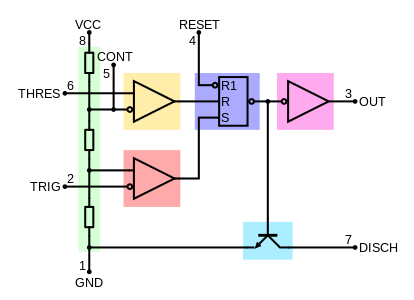
A collection of 555 circuits using the 555 timer as an astable oscillator with different duty cycles. In this category, we have handpicked some really useful 555 timer circuits which will be interesting to electronics engineering students and hobbyists alike. We connect a 100μf capacitor to the positive voltage supply and then to pin 2. The 555 timer ic is an integrated circuit (chip) used in a variety of timer, delay, pulse generation, and oscillator applications. Using the 555 timer ic in special or unusual circuits. Derivatives provide two or four timing circuits in one package.it was commercialized in 1972 by signetics. The ic can operate in three different modes such as astable, monotstable and bistable, because of which it can be adapted into many types of circuit designs like time delay circuits, pulse generation circuit, oscillator circuit and much more. If a 10uf timing capacitor is used, calculate the value of the resistor required to produce a minimum output time delay of 500ms. The output voltage from the chip is around 1.5 v lower than vcc when high and around 0 v when low. In 2017, it was said over a billion 555 timers are produced. We have seen in the last few tutorials that the 555 timer can be configured with externally connected components as multivibrators, oscillators and timers, with timing intervals ranging from a few microseconds to many hours. Interesting circuits you can make with 555 timer circuit. The block diagram of a 555 timer is shown in the above figure.
The values of r1 and c1 determine how long the output will remain high. 555 timer helpers schematic the addition of a capacitor to the trigger will not work for short output pulses as there is also a short delay in the recovery of the trigger terminal voltage. 555 timer ic is an integrated circuit used in a variety of timer, pulse generation circuit, and oscillator circuit applications. The 555 is also very versatile, and can be used. Let us discuss in detail about this circuit.
Cannot Understand The 555 Ic Reset Electrical Engineering Stack Exchange from i.stack.imgur.com 500ms is the same as saying 0.5s so by rearranging the formula above, we get the calculated value for the resistor, r as: 555 timer is an industrial standard ic existing from early days of ic. In this category, we have handpicked some really useful 555 timer circuits which will be interesting to electronics engineering students and hobbyists alike. Using the 555 timer ic in special or unusual circuits. This led will be switched on when button s1 is pressed and switched off when button s2 is pressed. If a 10uf timing capacitor is used, calculate the value of the resistor required to produce a minimum output time delay of 500ms. The output voltage from the chip is around 1.5 v lower than vcc when high and around 0 v when low. The 555 timer delay before turn on circuit we will build is shown below.
As we know 555 timer ic is one of the commonly used ic among students and hobbyists.
The 555 timer is a simple integrated circuit that can be used to make many different electronic circuits. The 555 timer delay before turn on circuit we will build is shown below. The second 555 timer helper will extend the timers output duration without having to use large values of r1 and/or c1. This circuit uses very basic components like 555 timer and 4017 counter. The standard 555 timer ic is made of 2 diodes. The output voltage from the chip is around 1.5 v lower than vcc when high and around 0 v when low. Its name is derived from three 5k ohm resistors ,connected in series used in it.the timer ic can produce required waveform accurately. There are simple circuits for beginners and advanced engineers. To understand the basic concept of the timer let' s first examine the timer in block form as in figure 1. 555 timer helpers schematic the addition of a capacitor to the trigger will not work for short output pulses as there is also a short delay in the recovery of the trigger terminal voltage. The circuit operates on 9vdc of power. We have a large collection of simple and advanced projects using 555 timer ic. 555 timer circuits (133) browse through a total of 133 555 timer circuits and projects including the timer's datasheet.


Posting Komentar
0 Komentar